DUK - Antennenverteiler AAD 10/4
Der Antennenverteiler schaltet 4 x aktive oder passive Antennen auf 10 x Empfänger
wobei die Antennenauswahl per Fernsteuerung oder auch Handbedienung erfolgen kann.
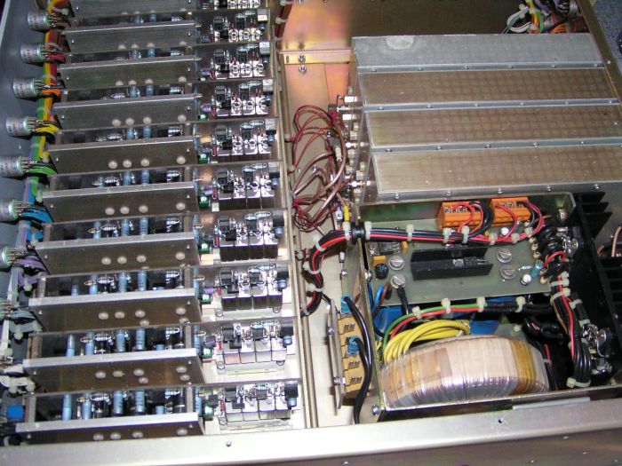
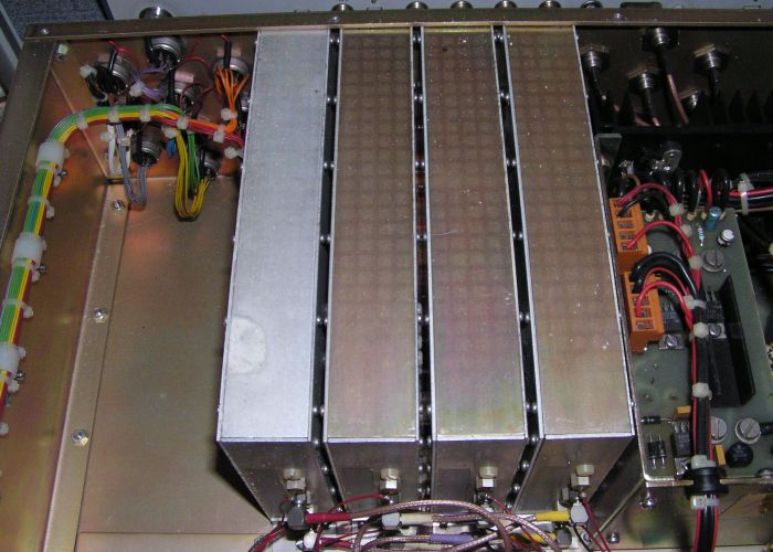
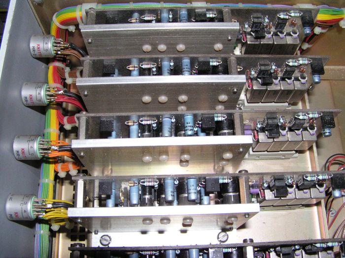
AAD 10/4 Ansicht innen

Pre-Amplifier / Channel Amplifier
Pre - Amplifier
Channel Amplifier
Discription Pre - Amplifier
The received HF – signal arrives at the input transformer T1 via the terminal X1 and the capacitors C28 and C29.
The supply of 39 Volt dc for the active antennas is connected to the antenna by switch S1, and passes the fuse F1 and the choke L1.
The pre – amplifier consists of two identical amplifier stages wich are connected to the input trafo via C24 resp. C30. Each of these stages feeds five channel amplifiers.
The funktion of the amplifier is as follows:
The HF – signal arrives at tha base of transistor V8 the quiescent current of wich is 25 mA. It is impressed by transistor V12. The diodes V9, V35, and V36 protect the circuit against too high input voltages. The variable resistor R10 controlling the operational point of the amplifier shall be adjusted untill the summation point V10/C20 measures half the battery supply voltage ( 39 V x 0,5=18,5 V )
From the emitter of V8 the signal is feed to the two bases of the final stage transistors V7 and V17.
The signal is coupled out via C22, C21, and C26 with low impedance in order to supply the cannel amplifiers.
The diode quartet V10 and the transistors V1, V3, V4, V6, V14, and V16 and their associated passive components form a control circuit for the temperature and cross modulation capacity of the final amplifier stage. The quiescent current in the final stage is given by the reference stage V6 and V16.
A differential amplifier consisting of V3 and V4 compares the currents in the final stage with the reference.
It controls the the positioning transistor V1 wich again adjusts the required base bias according to the operating contitions of the final stage
Discription Channel Amplifier
The RF – signals of the four antennas run from the four preamplifiers to the channel amplifier via the plug connection X1. A signal is chosen by the relais K1 – K4 wich are controlled by the rotary Switches at the front panel. This signal is led to the amplifier via C4.
Regarding the following circuit of the channel amplifier, please, rever to the discribing the circuits of the pre-amplifier, as they are identical.
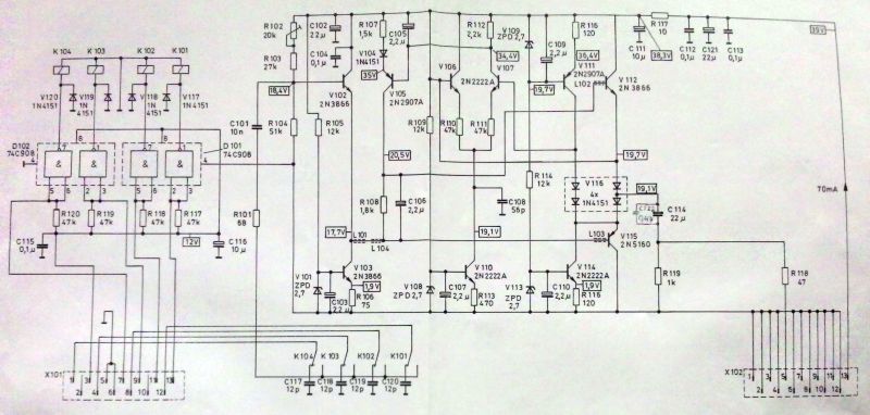
Circuit Pre - Amplifier

Circuit Channel Amplifier